Welcome to Yaming Technology
Production Lines for Automobiles, Motorcycles & Tricycles Email:[email protected]

Quotation Hotline
+86 135-2083-2251Welcome to Yaming Technology
Production Lines for Automobiles, Motorcycles & Tricycles Email:[email protected]
Quotation Hotline
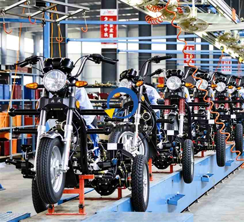
+86 135-2083-2251This assembly line adopts a modular overhead conveyor system, using orange truss structures as the primary support framework, paired with multi-point lifting fixtures to transport frames between workstations. The entire line follows either a U-shaped or linear layout, with inter‑station spacing calculated through ergonomic analysis to ensure an operating radius of 0.8–1.2 meters.
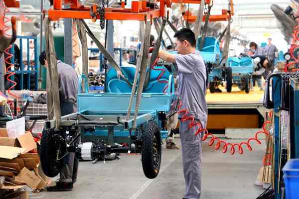
As visible in the image, the overhead conveyor track and the floor roller conveyor form a three‑dimensional logistics system: the aerial system handles long‑distance movement of the main frame, while the ground level serves as parts buffer zones and manual assembly passages. This “overhead + ground auxiliary” dual‑layer architecture effectively addresses the transfer challenges posed by the large dimensions and concentrated weight of tricycles (bare frames typically weigh 80–120 kg).
In the foreground of the image, the frame has completed preliminary installation of the front‑axle steering system and rear‑axle drive system. The black wheel‑tire assemblies employ a pre‑tightening process, with bolt torque controlled at the first‑stage standard (typically 60% of the final torque), reserved for subsequent stations to re‑tighten with calibrated torque wrenches. The exposed motor/engine mounting position beneath the frame indicates a rear‑engine, rear‑wheel‑drive layout—a typical configuration for cargo tricycles.
The blue cargo bed is suspended above the frame via lifting fixtures, where operators perform the body drop‑in operation. This station uses a “soft‑connection” positioning method—the fixtures are equipped with XY‑axis fine‑adjustment mechanisms, allowing ±15 mm positional compensation, which reduces the stringent demands on frame welding precision. The red spiral air hoses supply 6–8 bar compressed air to pneumatic tools, used for riveting or bolting the connection points between the cargo bed and the frame.
The red spiral hoses descending along the lifting fixtures are actually retractable air supply lines, with an extension ratio of approximately 1:4, accommodating a 1.5‑meter movement range between stations. This design eliminates the tripping hazards caused by traditional drag‑chain hoses on the floor, while reducing hose wear. Similarly, the vehicle’s electrical system employs pre‑laid wiring harnesses, routed during the chassis station phase, requiring only connector mating after body marriage is complete.
| Technical Parameter | Configuration Details |
|---|---|
| Load‑Bearing Method | Four‑point sling balanced suspension |
| Takt Control | Variable‑frequency drive, typical takt time 10–15 min/unit |
| Positioning Accuracy | Mechanical stop + manual fine‑tuning, repeatability ±5 mm |
| Station Lighting | Localized workstation lighting 300–500 lux, avoiding overall lighting energy consumption |
The design of the suspension fixtures is particularly ingenious: using webbing slings rather than rigid clamps accommodates the irregular frame contours while preventing paint‑surface damage. The fixtures connect to the main track via quick‑release hooks, enabling model changeover within 30 seconds—critical for the multi‑variant, small‑batch nature of tricycle production.
The entire assembly line follows the principle of “inside‑out, bottom‑up”:
Quality control employs a three‑tier model of “self‑check + mutual‑check + dedicated‑check.” Critical stations (such as brake‑line connections, front‑wheel alignment) feature torque‑monitoring points, with data entered into the MES system in real time, enabling per‑vehicle quality traceability.
From the on‑site layout, the upgrade potential of this line can be inferred:
If you have any questions or needs about the automated assembly line, please contact us via email: [email protected]