Welcome to Yaming Technology
Production Lines for Automobiles, Motorcycles & Tricycles Email:[email protected]

Quotation Hotline
+86 135-2083-2251Welcome to Yaming Technology
Production Lines for Automobiles, Motorcycles & Tricycles Email:[email protected]
Quotation Hotline
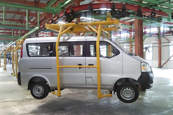
+86 135-2083-2251This manufacturing system is purpose-built for compact, multi-purpose commercial vehicles. Within the controlled environment of our assembly hall, painted body shells advance via an overhead conveyor network, sequentially acquiring interiors, powertrains, and chassis systems. The result is a fully functional, road-validated vehicle—engineered for reliability under intensive commercial duty cycles.
Unlike conventional assembly setups, this line emphasizes vertical integration and spatial efficiency, transforming raw painted bodies into market-ready microvans through a tightly choreographed sequence of mechanical and electrical integration processes.
The defining architectural feature of this line is the power-and-free overhead conveyor system, characterized by its red-and-green elevated steel framework spanning the production floor.
Key Engineering Advantages:
The system operates on a hybrid indexing model: continuous flow in high-throughput zones, with discrete stops at critical assembly stations. Carrier trolleys engage or disengage from the main drive chain at transfer points, allowing localized cycle adjustments without disrupting overall line rhythm.
Interior integration precedes chassis marriage. As bodies advance along the trim line, operators install complex subsystems in a structured sequence.
Primary Operations:
Pre-assembled instrument panels—integrating the steering column, HVAC ducts, wiring harnesses, and infotainment units—are positioned into the cabin. This modular approach consolidates dozens of individual components, significantly improving dimensional consistency and reducing cycle time.
Subsequent stations handle seating systems, headliners, carpeting, and interior trim panels. Given the microvan’s dual commercial/passenger role, flexible configurations (from two-seat cargo variants to seven-seat people movers) are accommodated within the same line architecture.
Side doors are detached early in the sequence and routed to dedicated sub-lines. This decoupling improves ergonomic access to the cabin interior and permits simultaneous door hardware installation, streamlining overall throughput.
While the trim line progresses above, the chassis line builds the vehicle’s mechanical foundation in parallel.
Sub-Assembly Modules:
Synchronization logic ensures the completed chassis module arrives at the marriage station precisely as the corresponding body shell reaches the same point.
The marriage station represents the pivotal moment where body and chassis unite.
Once united, the integrated vehicle transfers to the final assembly line for systems completion.
Post-marriage, the vehicle undergoes final mechanical and electrical integration.
Key Stations:
Before release, each vehicle undergoes rigorous functional testing.
Validation Sequence:
Line performance is governed by takt time—the rate at which vehicles must be completed to satisfy demand. Real-time monitoring systems track conveyor speeds, station cycle times, and andon signals to preempt bottlenecks.
Logistics Strategy:
Quality assurance is embedded throughout the process, not relegated to a final inspection point.
Core Elements:
This microvan final assembly line is a purpose-engineered ecosystem designed to convert painted body shells into robust commercial vehicles. Through synchronized takt-time pacing, JIT logistics, and rigorous quality gates, every process node—from interior trim installation to chassis marriage and end-of-line validation—contributes to a vehicle capable of withstanding demanding operational environments. The result is a product defined by precision, durability, and readiness for intensive commercial and passenger transport alike.