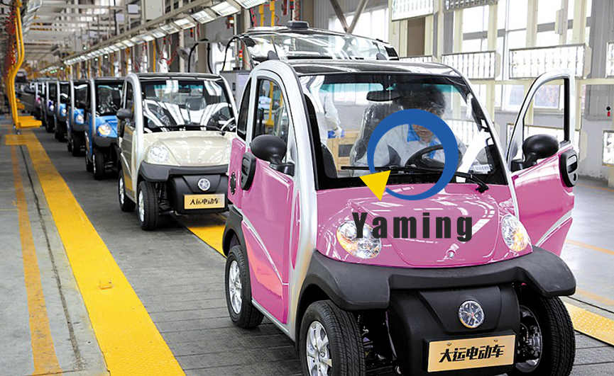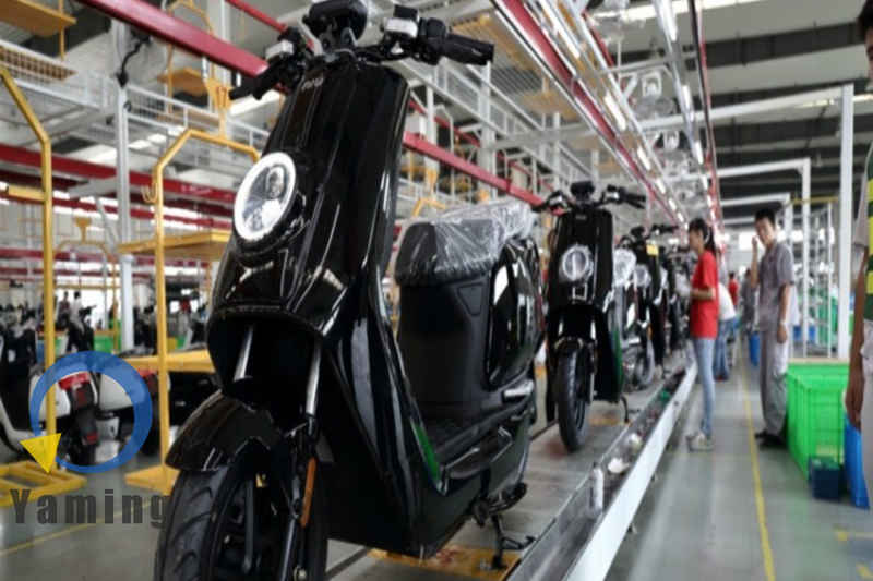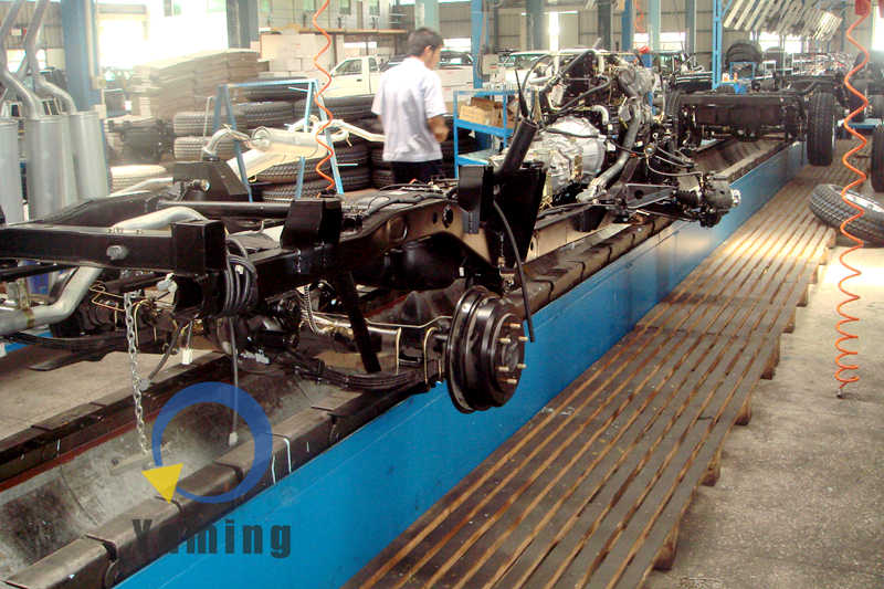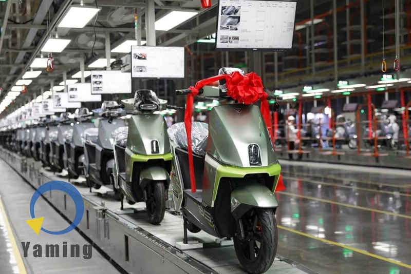
The Scooter assembly line consists of a floor slat chain conveyor system and a workstation operation system. The line body runs through the assembly workshop. Completed vehicles are arranged on the slat chain, sequentially passing through inspection stations and the off-line exit on the scooter assembly line.
The floor conveyor system adopts a slat chain conveyor line. The slat chain is formed by connecting multiple metal plates with hinges, creating a continuous annular conveying surface. The slat chain is installed in a ground trench, with its upper surface flush with the ground. The driving device is located at one end of the slat chain, consisting of a motor, a reducer, and a sprocket, driving the slat chain to run at a set speed. The tensioning device is located at the other end to adjust the slack of the slat chain. Fixtures are fixed on the upper surface of the slat chain. The fixtures are specially designed according to the scooter chassis structure; the front and rear wheels of the vehicle rest on corresponding support points, keeping the body in an upright state. The load capacity of the slat chain is designed according to the weight of the complete vehicle and the fixtures, and the chain and plates are made of steel. The running speed of the slat chain is set according to the production cycle time, and the dwell time at each station is fixed. The distance between stations is determined by the assembly content.
The assembly process is divided into multiple sections. The front section handles frame loading and chassis pre-assembly. The scooter frame is transported from the storage area or welding workshop to the starting point of the line body and manually placed on the slat chain fixtures. The frame enters the motor and transmission system installation station, where workers fix a hub motor or belt drive assembly in the middle and rear part of the frame. The motor is delivered to the station side by an independent conveyor line, and electric tightening tools are used for fastening, with torque values specified by process documents. Some models are equipped with dual motors, accordingly increasing the workstation operation content on the scooter assembly line.
The middle section performs electrical system assembly. Workers install the battery compartment, controller, wiring harness, and instruments on the frame. The scooter battery compartment is usually located under the seat bucket or the footboard. The compartment body is connected to the frame with bolts. The battery pack is delivered to the station side by the logistics system, and workers push the battery pack into the compartment and secure it. The wiring harness is routed along the frame cavity and trim clips, and connectors are plugged into corresponding sockets for the motor, controller, instrument, lights, sensors, etc. The instrument is installed in the middle of the handlebar or inside the front fascia, displaying speed, battery level, and fault codes. After the electrical connections are completed, workers conduct a power-on test at the inspection station to check motor operation, lights, instrument display, horn, and brake power-off functions.
The rear section carries out the assembly of exterior parts and the running system. Workers install the front fascia, side panels, seat bucket, front fender, and rear fender on the frame. Shell parts are produced in the injection molding workshop and delivered to the material racks beside the line via turnover boxes. Some exterior parts are bulky, so dedicated material racks are set up beside the stations. The seat assembly is installed after the seat bucket, including the seat cushion, hinges, and locks. The handlebar assembly includes the steering column, brake levers, twist throttle, lights, and rearview mirrors, which are installed and adjusted by workers at the front-end station. Tires and wheels are installed at independent stations, where workers use special tools to mount tires and assemble the braking system.
The final section conducts vehicle commissioning, testing, and off-line. Workers perform functional tests on the complete vehicle at the end of the slat chain to check acceleration performance, lights, horn, steering, and braking performance. After passing the tests, some vehicles have identification ribbons tied to them, indicating that assembly is complete or a specific batch has been reached. The vehicles leave the line at the end of the slat chain and enter the waiting area or packaging area. Packaging operations include installing protective materials, securing the vehicle, boxing, and labeling.
A suspended kanban system is installed above the line body. Metal rods or rails are mounted on the workshop ceiling, and kanbans are hung above the conveyor line via hooks. The kanban content consists of work instructions, displaying assembly steps, parts diagrams, and inspection points of that station in graphic form. The kanban size is determined by the content volume and installed facing the workers’ line of sight. Workers can look up to check process requirements during operations. Kanban content is updated according to model and process changes.
A tool suspension system is also installed above the line body. Rails are mounted on the workshop ceiling, equipped with pulleys and balancers for hanging pneumatic and electric tools. Air pipes and cables are connected to the tools via spiral tubes. Workers pull the tools within the working range, and the tools automatically return to position when released. The length of the spiral tube is determined by the station coverage. Lighting fixtures are installed above some stations, arranged along the conveying direction.
The station layout is arranged according to the assembly sequence. Each station is equipped with tool racks, parts boxes, and material racks. The material racks store parts and fasteners required for the station, with the number of layers and spacing designed according to the size of the parts. Yellow safety lines are marked on the station floor to divide the work area and passageways. Station screens are installed at key stations, displaying production cycle time, quality prompts, and call information.
The control system consists of a PLC and a touch screen. The PLC controls the start, stop, running speed, and positioning accuracy of the slat chain. The touch screen is installed in the central control cabinet or beside the line body, allowing operators to set parameters and view status through the interface. Multiple emergency stop buttons are set on the conveyor line, distributed on both sides of the stations and at the central control position. When the emergency stop is triggered, the slat chain stops running, and it restarts after the fault is eliminated and reset. The line body is equipped with audible and visual alarms to indicate equipment abnormalities or shift change information.
The cycle time of the scooter assembly line is determined according to the production capacity plan, ranging from tens of seconds to several minutes. The line length is calculated based on the number of stations, station spacing, and workshop dimensions. The width of the slat chain, plate thickness, and drive power are selected according to the load requirements. The spacing of the fixtures is determined according to the vehicle length to ensure no interference between adjacent vehicles.
This assembly line is specifically used to produce scooter-style electric two-wheeled vehicles. The vehicle is characterized by a flat floorboard design, with the battery and controller arranged under the footboard or seat bucket, and the exterior wrapped in integral injection-molded parts. By replacing fixtures and adjusting operation content, the scooter assembly line can be compatible with scooter models of different wheelbases and wheel diameters. The slat chain conveying method is widely used in this product line, providing a continuous ground operation platform where workers stand in fixed positions to assemble the moving frames. All systems operate in coordination through a control program, constituting a complete scooter assembly line for mass production.
Technical Parameter Supplement Table for the Scooter Assembly Line
|
System Category |
Key Parameter Item |
Typical Technical Indicators/Description |
|---|---|---|
|
Floor Conveyor System (Slat Chain) |
Conveying Medium |
High-strength steel slat chains with anti-slip wear-resistant pads on the surface, adapting to the heavier self-weight of scooters on the scooter assembly line. |
|
Running Speed |
Usually variable frequency adjustable within 0.5 ~ 5 m/min. |
|
|
Load Capacity |
Single station load capacity usually 200kg ~ 800kg and above. |
|
|
Line Width |
Standard range 1000mm ~ 1500mm (adapting to scooter frame width and panel installation space). |
|
|
Auxiliary Supply System |
Air Supply Pressure |
Suspended red-white spiral air hose, standard pressure 0.4 ~ 0.6 MPa. |
|
Power Supply Configuration |
220V universal sockets, pneumatic quick couplings, and 380V power interfaces configured for each station. |
|
|
Tool Distribution |
Equipped with tool hanging boards with balancers to support the use of heavy-duty torque wrenches and electric tools. |
|
|
Overall Production Line Indicators |
Production Cycle Time |
Mainstream range 90 ~ 180 seconds/vehicle. |
|
Positioning Accuracy |
Station stopping accuracy usually required ≤ ±1mm. |
|
|
Key Process Equipment |
Angle Valve Control |
Dedicated angle valves configured in the braking lines and pneumatic test circuits for quick on/off switching and fine-tuning of air pressure circuits. |
Contact information
- If you have any questions or needs about the automated assembly line, please contact us via email: [email protected]