1. Overview
As the core powertrain of an automobile, the engine manufacturing process places extremely high demands on the process planning and takt time design of the engine assembly line. From raw materials to the final off-line of the complete engine, the entire process chain can be divided into four major stages: precision machining of components, sub-assembly, final assembly, and testing & verification. Before the final assembly stage of the engine assembly line commences, a large number of core components must undergo rigorous pre-processing procedures. The quality of these precision machining processes directly determines the assembly accuracy and overall engine performance in the subsequent engine assembly line final assembly stage.
First is the blank forming and machining of core components. The cylinder block and cylinder head upstream of the engine assembly line are typically made of cast iron or aluminum alloy. After casting (sand casting or high-pressure die casting), they enter high-precision machining centers for dozens of processes including plane milling, cylinder bore honing, drilling, and tapping, to ensure that the flatness of all mounting surfaces, the roundness of cylinder bores, and surface roughness reach micron-level precision. Crankshafts and camshafts are mostly made of forged steel or ductile iron, undergoing forging, quenching and tempering, rough machining, fine grinding, and dynamic balance correction to guarantee journal dimensions and rotational accuracy. Connecting rods undergo forging, fracture splitting, mating surface machining, and small-end bore fine boring; pistons require casting, skirt outer diameter machining, pin bore fine boring, and piston ring groove machining, followed by weight grouping and matching. In addition, peripheral components such as the fuel injection system, turbocharger, oil pump, water pump, and intake/exhaust manifolds must each go through independent precision manufacturing and quality inspection processes before entering the engine assembly line final assembly stage.
Next is component sub-assembly. To improve the production takt of the engine assembly line’s main final assembly line, structurally complex modules are pre-assembled on dedicated sub-assembly lines. Typical sub-assemblies include: cylinder head sub-assembly (installing valves, valve springs, hydraulic lifters, camshafts, etc. into the cylinder head to form a complete cylinder head assembly), piston-connecting rod sub-assembly (assembling the piston, piston rings, piston pin, and connecting rod with weight matching), and crankcase sub-assembly (installing the crankshaft, main bearing caps, thrust washers, etc. into the lower half of the cylinder block or crankcase).
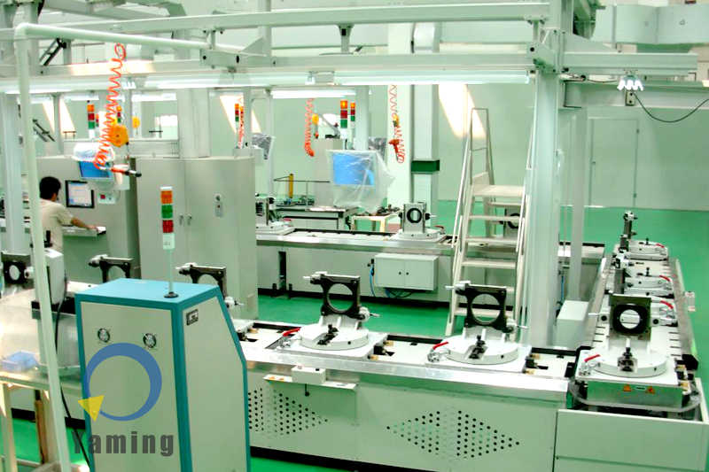
Upon entering the final assembly stage, all sub-assemblies converge onto the engine assembly line to complete the final engine assembly. The automated final assembly system of the engine assembly line shown in the image is a flexible automated assembly system applied to heavy machinery or engine final assembly. Its core design aims to balance automated high-efficiency operation with the ergonomics of manual labor. The engine assembly line adopts a modular pallet-free friction roller conveyor system, coupled with dedicated heavy-duty traveling fixtures (such as the black ring-shaped brackets and bases shown in the image), capable of carrying and precisely positioning large workpieces. By integrating PLC logic control with distributed signal towers, takt control, status monitoring, and rapid fault response of the assembly process are achieved.
The specific process route typically includes the following core workstations:
- Cylinder Block Loading and Turning: After cleaning, the cylinder block is hoisted by conveyor or overhead crane onto the engine assembly line’s traveling fixture, conveyed sequentially via the friction roller system, and turned at designated stations for bottom or top assembly.
- Crankshaft and Piston-Connecting Rod Assembly: At this station, the engine assembly line installs the crankshaft into the cylinder block’s main bearing seats, then uses dedicated tools or manual methods to install the piston-connecting rod assemblies into the corresponding cylinder bores in firing order, tightening the connecting rod bolts to specified torque and angle.
- Cylinder Head Assembly and Timing System Installation: The engine assembly line employs multi-spindle tightening machines or high-precision torque tools to hoist the cylinder head assembly onto the cylinder block, tightening cylinder head bolts using a multi-step torque + angle method. The timing chain/belt, tensioner, and camshaft phaser are then installed to ensure accurate valve timing.
- Peripheral Component Assembly: The engine assembly line sequentially installs the oil pump, water pump, fuel rail, injectors, throttle body, alternator, starter, intake/exhaust manifolds, oil pan, etc., and completes the connection of various sensors, wiring harnesses, and pipelines.
- Sealing and Leak Prevention: The engine assembly line applies sealant or installs gaskets on critical mating surfaces, and conducts online leak tests (such as oil gallery pressure hold tests, water jacket airtightness tests, vacuum sealing tests, etc.) to ensure no leakage.
After final assembly on the engine assembly line is completed, the engine must undergo testing and off-line procedures. This typically includes a Cold Test (the engine is driven by a motor without ignition to detect mechanical resistance, compression pressure, leaks, and sensor signals) or a Hot Test (the engine is actually fired to measure power, torque, emissions, and abnormal noises). Upon passing inspection, the engine assembly line performs final visual inspection, cylinder block painting (optional), labeling, and the product is either stored in the warehouse or directly sent to the vehicle assembly line.
2. Details
- Workpiece Positioning and Traveling Fixtures: The engine assembly line conveyor does not use traditional pallets. Instead, it adopts direct conveying or support positioning via large dedicated fixtures (black ring-shaped structures and bases). This design ensures the rigidity of heavy components during assembly, prevents displacement, and allows operators easy access to the work surface from multiple angles.
- Pallet-Free Friction Roller Conveyor System: The bottom of the engine assembly line uses an open friction roller conveyor structure. Compared to enclosed double-speed chains, this facilitates the loading and unloading of heavy workpieces, offers higher load capacity, and is easier to maintain. The line features bidirectional transmission and automatic stop functions, ensuring the independence of each workstation’s operations.
- Human-Machine Interaction and Workstation Layout: Multiple independent workstations are arranged along the engine assembly line, equipped with tilted control panels and push-button boxes. This layout fully considers ergonomics, enabling operators to perform heavy or delicate tasks such as assembly, tightening, or self-inspection in a comfortable posture.
- Distributed Status Monitoring: Multi-layer three-color signal towers (red, yellow, green) and buzzer alarm devices are suspended above each key workstation of the engine assembly line. This distributed I/O design provides real-time feedback on the station’s operating status (running/waiting for material/fault/completed), greatly improving the agility of production line anomaly handling.
- Modular Top Frame and Pipeline Distribution: A lightweight aluminum alloy or stainless steel tubular frame is built on top of the engine assembly line to suspend lighting fixtures, pneumatic spiral tubes (orange pipes), and cables. This tubular modular design makes later workstation adjustments or equipment expansion extremely convenient.
3. Parameters
(Note: The following parameters are inferred values based on typical industrial standards for similar engine assembly lines (heavy-duty automated assembly lines). Specific values are subject to the actual equipment nameplate or technical agreement.)
|
Parameter Category |
Item |
Reference Specification / Description |
|---|---|---|
|
Physical Specifications |
Conveyor Height |
800mm – 1100mm (adapted to ergonomic operating height of engine assembly line) |
|
Conveyor Width |
500mm – 800mm (dual-row friction roller structure) |
|
|
Station Spacing |
1800mm – 2000mm (meets space requirements for heavy equipment assembly and circulation) |
|
|
Performance |
Conveying Speed |
5 – 15 m/min (variable frequency stepless speed regulation) |
|
Takt Time |
≤ 90 – 120 sec/piece (depending on the complexity of the specific assembly process) |
|
|
Load Capacity |
≥ 500 kg/pallet (including the weight of heavy workpieces and fixtures) |
|
|
Control Precision |
Positioning Accuracy |
± 0.1 mm (friction rollers combined with mechanical stoppers) |
|
Electrical System |
Control Core |
PLC (Programmable Logic Controller) + HMI (Touchscreen Human-Machine Interface) |
|
Drive Method |
Three-phase asynchronous motor + reducer |
|
|
Signal Transmission |
Distributed I/O modules + Industrial Ethernet/Fieldbus |